|
Product Details:
|
| Tx: | Support 10Gbase-T / 5Gbase-T / 2.5Gbase-T / 1000base-T On Line Port | Rx: | Support 10Gbase-R On Host Port |
|---|---|---|---|
| Footprint: | Hot-pluggable SFP Footprint | Interface: | RJ45 |
| Power Supply: | +3.3V DC | Cable: | 10 Gigabit Ethernet Over Cat 6a Cable |
Features
¨ Support 10Gbase-T / 5Gbase-T / 2.5Gbase-T / 1000base-T on line port
¨ Support 10Gbase-R on the host port
¨ Hot-pluggable SFP footprint
¨ Compact RJ-45 connector assembly
¨ RoHS-compliant and lead-free
¨ Single +3.3V power supply
¨ 10 Gigabit Ethernet over Cat 6a cable
¨ Ambient Operating temperature: 0°C to +70°C or -40°C to +85°C
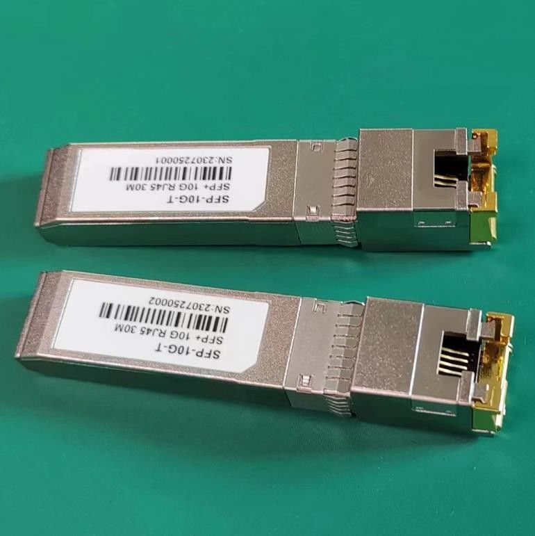
![]()
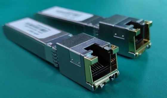
OP-SFP-10G-T Copper Small Form Pluggable (SFP) transceivers are based on the SFP Multi Source Agreement (MSA) . They are compatible with the 10Gbase-T / 5Gbase-T / 2.5Gbase-T / 1000base-T standards as specified in IEEE Std 802.3 . FR-SFP-10G-T uses the SFP's RX_LOS(must be pulled up on host) pin for link indication. If pull up or open SFP's TX_DISABLE pin, PHY IC be reset.
Cable Length
| Line Port | Cable | Reach | Host Port |
| 10Gbase-T | CAT6A | 30m | 10GBase-R |
| 5Gbase-T | CAT5E | 50m | 10GBase-R |
| 2.5Gbase-T | CAT5E | 50m | 10GBase-R |
| 1000base-T | CAT5E | 100m | 10GBase-R |
Pin Descriptions
| Pin | Symbol | Name/Description | Ref. |
| 1 | VEET | Transmitter Ground (Common with Receiver Ground) | 1 |
| 2 | TFAULT | Transmitter Fault. Not supported. | |
| 3 | TDIS | Transmitter Disable. Laser output disabled on high or open. | 2 |
| 4 | MOD_DEF(2) | Module Definition 2. Data line for Serial ID. | 3 |
| 5 | MOD_DEF(1) | Module Definition 1. Clock line for Serial ID. | 3 |
| 6 | MOD_DEF(0) | Module Definition 0. Grounded within the module. | 3 |
| 7 | Rate Select | No connection required | |
| 8 | LOS | High indicates no linked. low indicates linked. | |
| 9 | VEER | Receiver Ground (Common with Transmitter Ground) | 1 |
| 10 | VEER | Receiver Ground (Common with Transmitter Ground) | 1 |
| 11 | VEER | Receiver Ground (Common with Transmitter Ground) | 1 |
| 12 | RD- | Receiver Inverted DATA out. AC Coupled | |
| 13 | RD+ | Receiver Non-inverted DATA out. AC Coupled | |
| 14 | VEER | Receiver Ground (Common with Transmitter Ground) | 1 |
| 15 | VCCR | Receiver Power Supply | |
| 16 | VCCT | Transmitter Power Supply | |
| 17 | VEET | Transmitter Ground (Common with Receiver Ground) | 1 |
| 18 | TD+ | Transmitter Non-Inverted DATA in. AC Coupled. | |
| 19 | TD- | Transmitter Inverted DATA in. AC Coupled. | |
| 20 | VEET | Transmitter Ground (Common with Receiver Ground) | 1 |
Notes:
1. Circuit ground is connected to chassis ground
2. PHY disabled on TDIS > 2.0V or open, enabled on TDIS < 0.8V
3. Should be pulled up with 4.7k - 10k Ohms on host board to a voltage between 2.0 V and 3.6 V. MOD_DEF(0) pulls line low to indicate module is plugged in.
Contact Person: Arthur Shaw
Tel: +86-13510877340
Fax: 86-755-25336378